


Page last Modified:
Wednesday, April 18, 2007 12:28:41 PM - Views

Neptuno Mod: Changing the colors of the Needles
Neptuno writes >> Do you ever look at your cluster and say..... Hmmm I wish there was more color in there? Well I did and decided to do some needle painting. A local rocco head SPscirocco gave me this idea so I am not taking credit for this mod, for the exception of the write up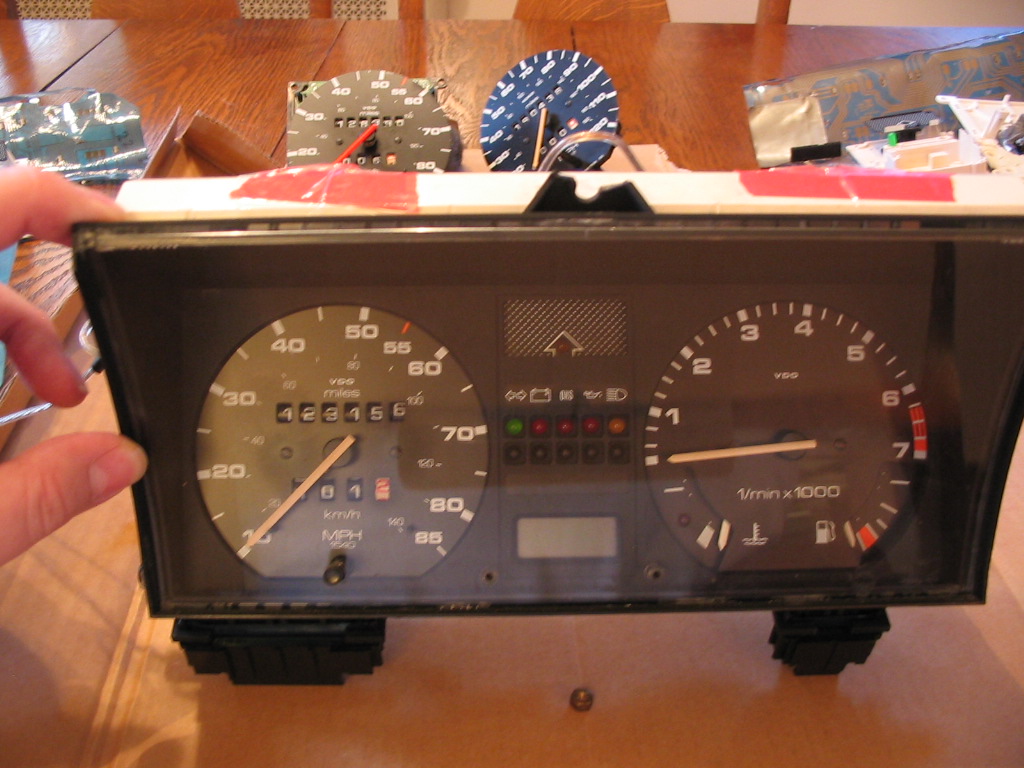
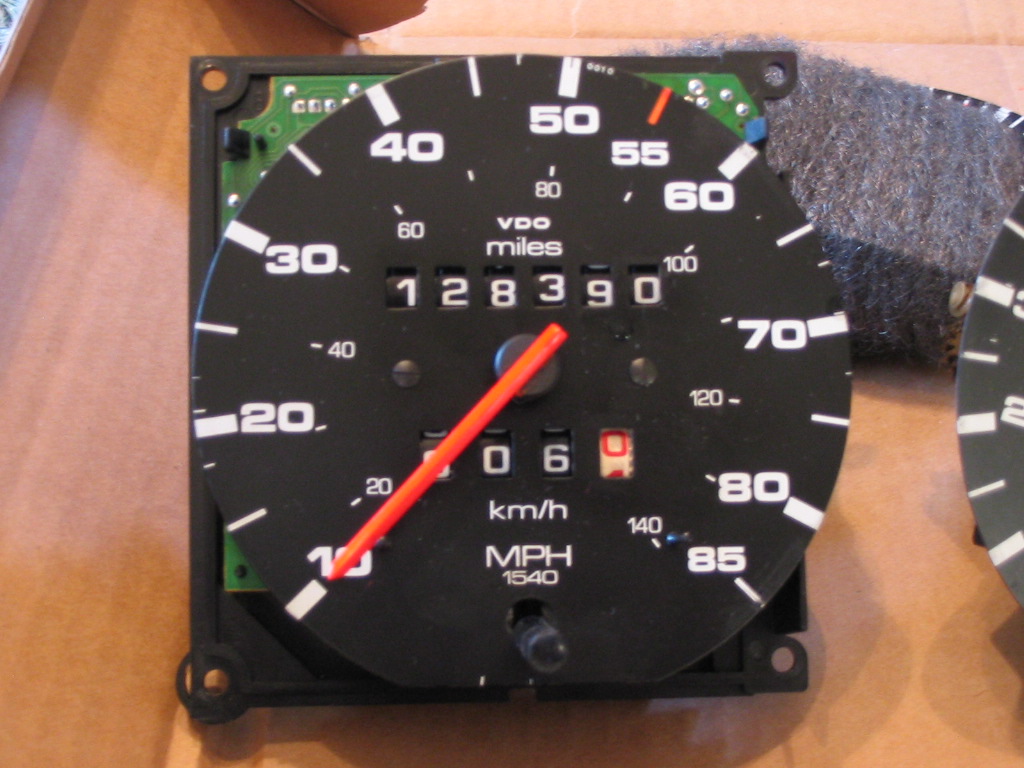
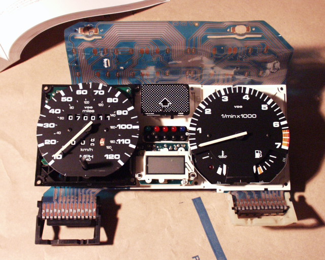
<1. Ok here is my boring cluster out of the car
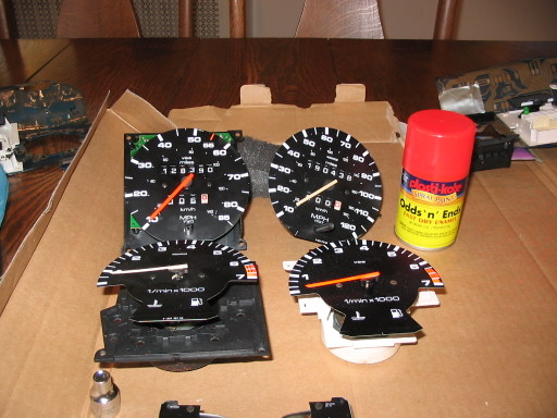
>2. If you are like me then maybe you have lots of bits and pieces of cluster laying around that you can prep some before installation otherwise you will have to paint and then assemble the whole thing.
Timbo adds >> It really helps to go to the junkyard and get a cluster from the same year/model so you can practice disassembling the cluster without breaking it!
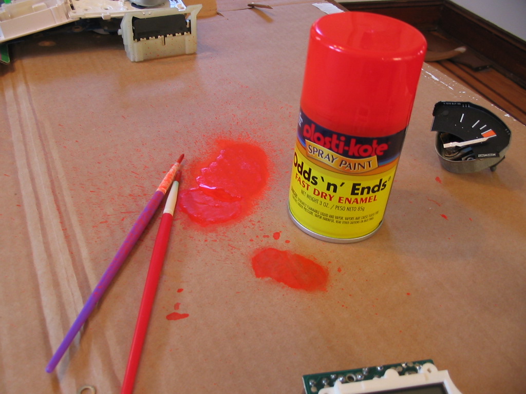
<3. The paint used is some odds and ends found at the local wally world. It is fluorescent orange and seems to match quite well with the stock orange on the cluster.
so take the cluster apart per ATS tech note that now lives in Timbos site [Timbo writes >> heh - It's right below]
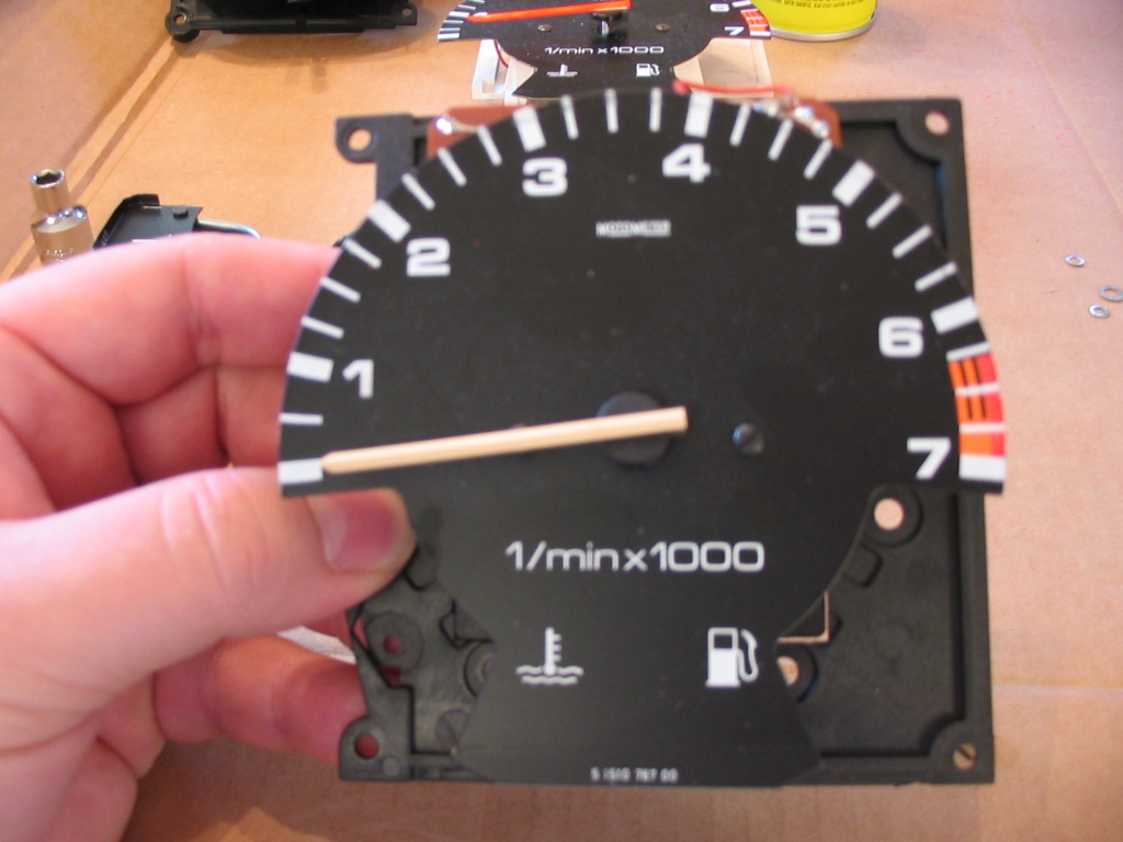
<4. Ok - that was the hard part. Now here is a Unpainted tach
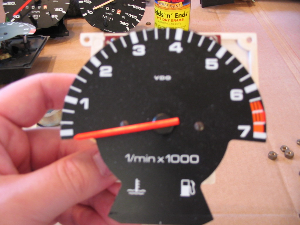
>5. After a little paint applied by a brush after spraying on a piece of cardboard the needle should look like this also noticed that I separated the fuel and water temp gauges from this picture. I have better access to those needles for painting
>6. here is a speedo needle painted
Just repeat the process until you get all the needles painted. If you have never played with the cluster before work slowly and be patient. Put everything back together.
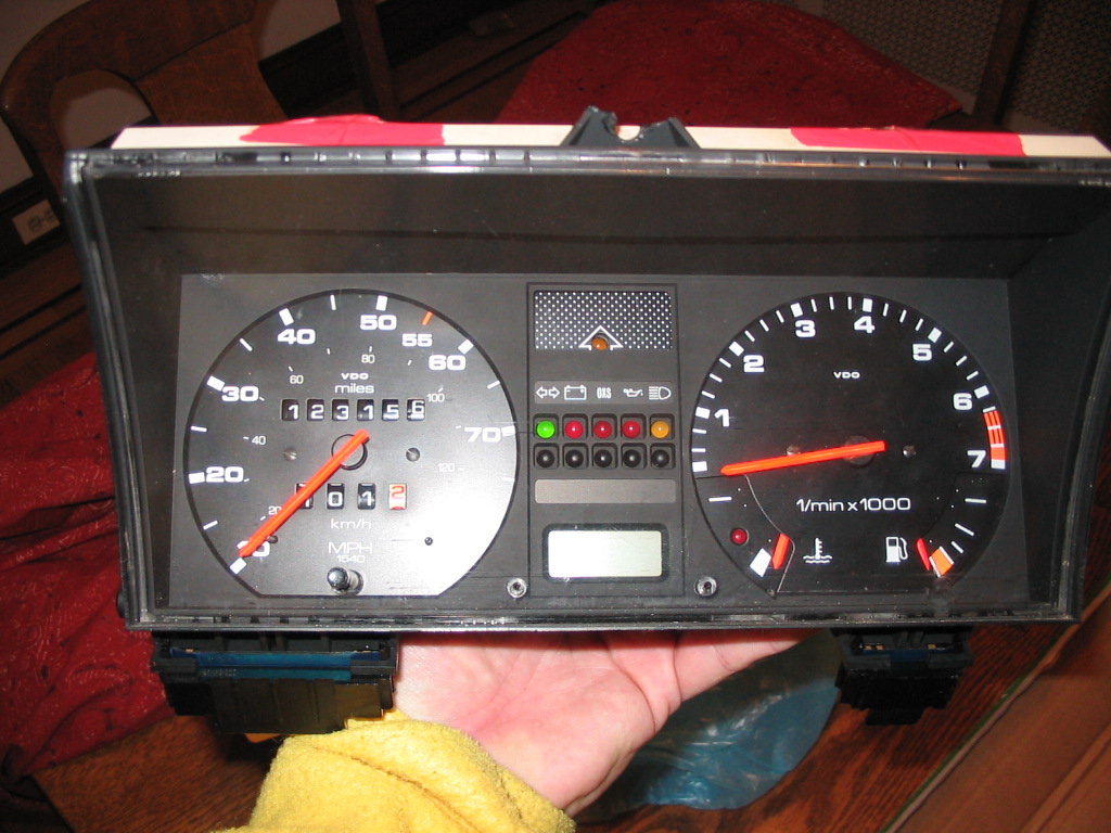

<7. Here is a finishing shot
<8. Now here it is in the car
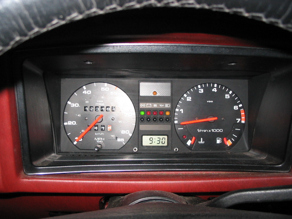
<9. This one shows it with the lights on.
That #9 shot really doesn't do justice to all the work. There is something about the blue LED's that I can never make it look like it looks in real life....which is 100 times better. [Timbo writes >> I tried to make the image better]
[Link to the VWVortex Thread that this mod is from]
| Remove the 2 screws holding the plastic cover of your instrument cluster trim | |
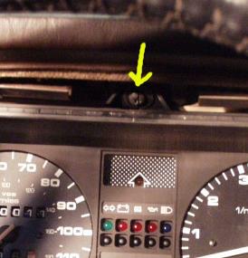 |
Unscrew the dash mounting screw (location shown on picture) |
|
|
Remove the under dash leg protector board, my particular car does now have the under the dash tray anymore so I have not put that into this tech note, sorry, check service manual for that. The picture indicates the location of the three (3) plastic pop-out plugs, then simply pull it out forward. |
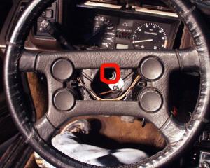 |
Pop the center piece of the steering wheel with a flat screwdriver and using a 24 mm socket, unscrew the center bolt on the middle of the steering wheel ( shown in circle in the picture) |
| Unplug the Speedometer cable (pinch and gently pull the plug to remove it), the power connection next to it, as well as the 2 large connectors at the base of the instrument panel. (one on each base corner of the box), simply pull instrument cluster out you might find that the plastic (covered with a soft rubber) pivot points at the base of the instrument cluster make is a little hard to remove it, think diagonals (grin) and take your time. it will come out. | |
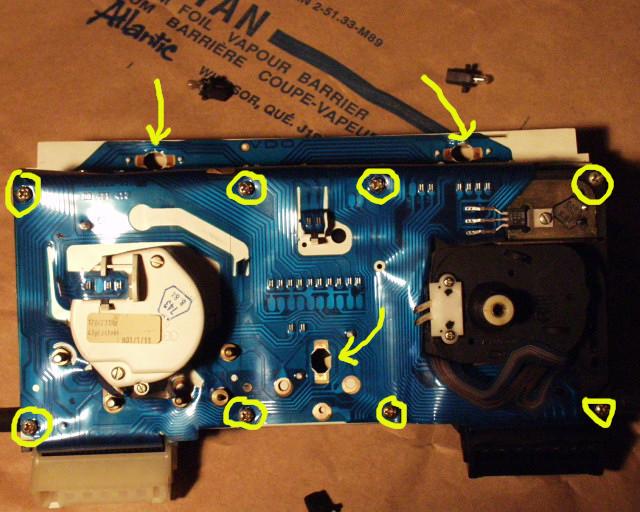 |
flip the instrument cluster over on a large flat area, the picture shows; arrows indicating the location of the 3 bulbs that need to be removed, and replaced if required (as I did) also indicated are the 8 screws that need to be removed, once that is done, gently lift the PCB plastic from pins and pegs (located near top of cluster bulbs holes. |
|
|
Flipping the Cluster on it side, dials facing you, gently pop out the connector plugs from their sockets |
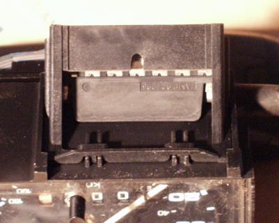 |
This is a close up of one of the connectors and how it should simply slide out of position to release itself from the cluster box |
 |
There! the dial cluster out from the instrument cluster box. Now the fun begins! |
|
|
Now flipping the cluster box on its side, you can see the location of the plastic holding points that need to be shaved off using an x-acto knife to release it from the box. |
|
|
Now that the color filter holder is free, this picture display the last few plastic points that need to be shaved to be able to release the color filter from it. |
|
|
This picture shows the color filter removed from the holder. |
|
|
I got my plastic at a local library store, and found the colored plastic in the folder section, it is meant to hold a couple of sheets inside of it. how to make a new color filter for the instrument cluster, draw it out with a marker and cut it out. it is that simple! |
|
|
Replacing the new color filter in position, I use a few drops of crazy glue on the cross post which it sit on to make it hold in place. |
| Reassemble the new color filter box back unto the instrument cluster box, again I used a few drop of crazy glue to hold it in place | |
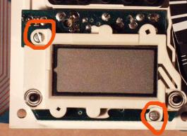 |
Next you need to access the LCD clock on the instrument cluster and unscrew the 2 screws marked in the picture |
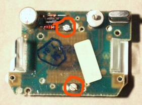 |
Flip the clock over and unscrew the 2 screws indicated in the picture, be careful and take you time, if you break the mounting points of the LCD connector, you will need to replace the LCD panel itself. take your time taking this little cluster apart. |
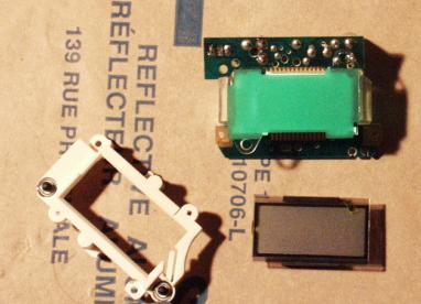 |
Here is the clock cluster apart, as you can see the last color filter to be change is just sitting under the LCD panel itself, remove it now. |
 |
As I did with the previous color filter, I simply marked it out with a marker and cut it out with an x-acto knife. |
 |
Here you see the newly cut out color filter placed back in the place of the original green one. Now reassemble the clock back up unto the instrument cluster your done! Re-assemble the instrument cluster together and assemble it back into your dash using reverse methodology |
|
|
Here is the final product, the lights at a dimmed strength (for night driving) |
|
|
Here is the final Product the lights being at full strength. NOTE: The clock is not functional on this image because I am having a "short" issue on fuse # 3, (next project to fix on the car) stay tuned. |
Well after looking at my nice amber colored instrument cluster, I kept being nagged about my heater control green settings, so I decided to do something about it. Now my heater control panel matches my dash. This is simple and took me 30 minutes taking my time.
|
|
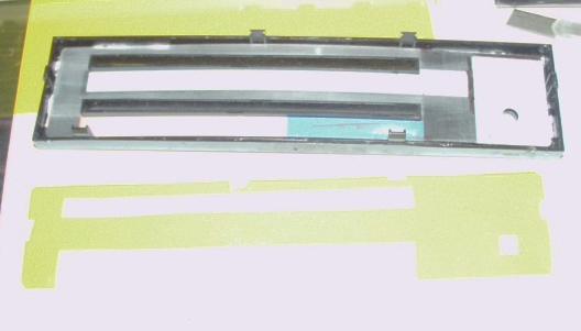
I start this tech tip after you have removed the 2 control slide buttons by pulling them out and removing the rotating speed control button from the panel, disconnecting the bulb. Here the first picture shows the back side of the heater control panel, using a small screwdriver or thin blade pry the white inner shape from the black outer shell, this is slow going process as you really don't want to break this white plastic backing has this is what holds everything together. |
 |
Here is the backing taken off from the main front part, inside you will find a hard clear plastic holding a thinner colored plastic film. Remove the clear plastic backing and pull out the thin colored one out. |
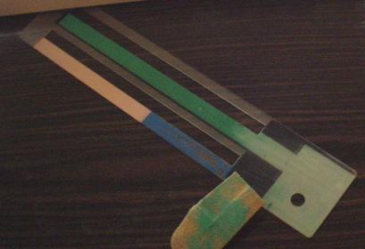 |
The interesting fact about the way this was painted, is that the black, red and blue are painted on the front of the panel (facing towards the cabin) and the green paint is on reverse side (towards the inside of the dash) this makes our life of changing the coloring of all the lettering and numbers and easy one, I use # 0 ultra fine sand paper and worked the green color paint off the plastic film. |
|
|
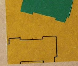
Once you have the green paint off the back of the plastic film you are now ready, selecting a color of your choice, I chose one that matched my instrument cluster coloring I did in the past, Lay it out on the new colored plastic film and outline the form of the original one. Please note that the Hot/Cold colored temps control on the new amber film has been traced out (i.e.: no colored plastic behind it. I did this to ensure that the new amber coloring would not change the painted colors on the film. now cut it all out. |
 |
You see what I mean about the hot/cold indicating paint cutout on this picture, also note that I did some notches for the few guides that are in the black front part of the control panel, permitting ease of install. Now install the first original film in, put the new colored film behind it, slide the hard clear plastic to hold it all down and close the white cover back the way it was, a few carefully placed (I use six (6) spots of crazy glue to hold the white backing in place.. remount in your console, and Voila! your done. |
Back To Top |
|
How to Change the Bulb in late-style Heater Controls
Special Thanks to sciroccojim for this technote...
As always, click the thumbnails to enlarge the picture
So, in case you didn't know, MKIIs made prior to about 87 (not sure) have an easily removable climate control panel illumination bulb, vs. later ones, which appear to have a non-replacable bulb. Not true - it can be replaced!Replacing the bulb on a later one is not as simple as the earlier models, but it's no big deal.
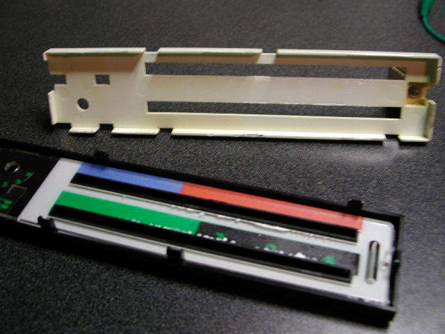
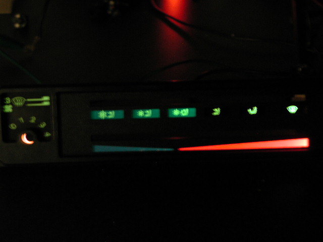
Here's the type I'm referring to. It has icons for each position, rather than words.

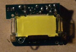
The white panel on the back is glued on, but you can pry it loose:
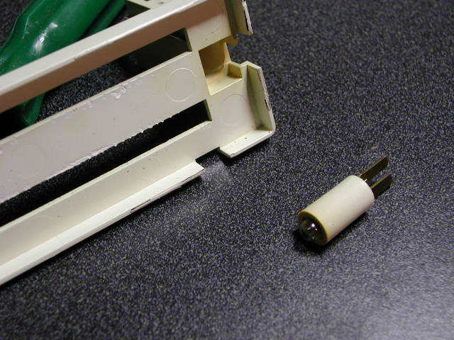
Here's the cool part. Maybe you didn't know, but the bulb and its housing can be removed from the panel. Just push on the terminals from behind and remove it:
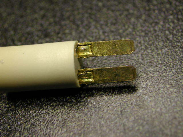
The wires connecting to the bulb are soldered (welded) to the terminals, so just take a mechanic's pick and break 'em loose:
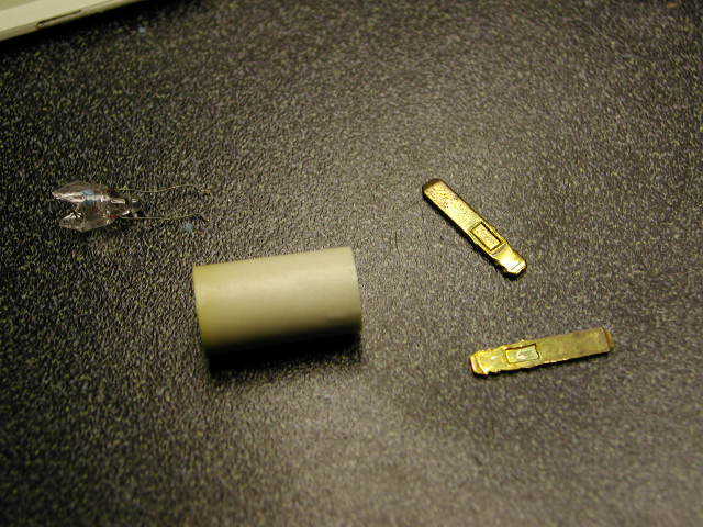
Terminals out, bulb out (broken...oops):
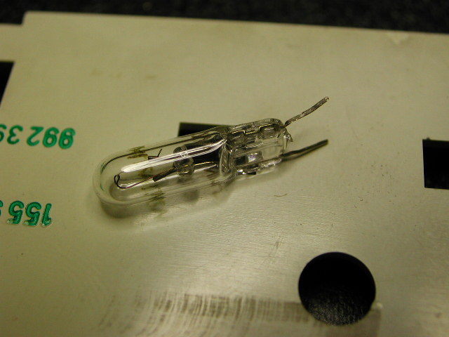
Here's a bulb. Unfortunately, I had cut the leads on it for another project, so they're a bit short, but I was able to make it work. This bulb is a good bit longer than the one that came out. I had to grind the nipple off of the underside of the bulb to keep it from sticking out too far:
Not pictured: Just stick the bulb into the socket so the leads stick out the back. Then push the terminals back in and the leads will make contact with the terminals.
The bulb still stuck out too far, so I made a little hole in the panel for clearance:
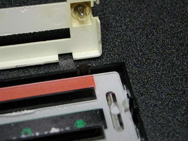
Groovy:
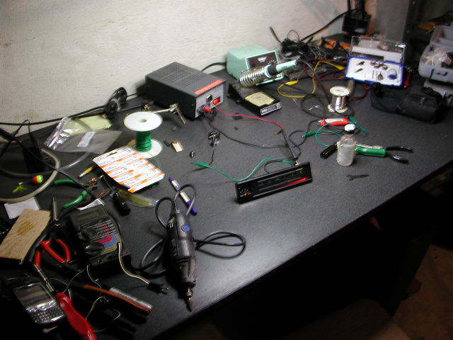
Cluttered workbench:
[Back to Top] [Index] [VWC Forums] [Contact/Donate]
Remember, If you need help with any of these technotes -Contact Me!
We are not responsible for damages caused while following the directions in these pages. These pages are for informational use only.
This site is in no way affiliated with or endorsed by Volkswagen of America or VW AG. Volkswagen and the VW logo are registered trademarks of Volkswagen
AG. To visit the official Volkswagen sites go to Volkswagen Germany
or VW of America.
All original images and content Copyright © 2001-2005 Eric Soltwedel, Tim McConnell and vintagewatercooleds.com, all rights reserved.
Not all of the pages comply with the new standards yet. I have the links here for debugging purposes.
![]()
![]()
![]()
About the Standards and Scripts