


Page last Modified:
Thursday, February 23, 2006 07:39:39 PM - Views

[CIS-E Mixture] [Digifant II Mixture]
[Fuel Enrichment for CIS-E 16v]
BETA TECHNOTE v0.4 - OPEN FOR PEER REVIEW:
Comment on this technote on the VWVortex Thread or the VintageWatercooleds.com Forums Thread.
Oxygen Sensor
About Oxygen Sensors
Oxygen sensors help the computer make corrections in the car's air/fuel ratio by measuring the oxygen content in the exhaust. Oxygen in the exhaust is a good measure of the efficiency of the combustion. The computer then adjusts the air/fuel accordingly. In CIS cars - it changes the duty cycle (On-Off) of the frequency valve, which is the buzzy thing on the back of the fuel distributor on top of the air box. In CIS-E cars, it adjusts current to the DPR (Differential Pressure Regulator) to change the pressure in real-time.
Oxygen sensors go bad for a few different reasons. Leaded fuel will kill them. RTV silicone hurts them, and lots of soot will clog them. The wire can also become frayed and broken and not carry the proper amount of voltage. On newer cars with heated sensors, the heater may break, causing the warm-up time to take longer.
Testing the Oxygen sensor
Using a voltmeter, and the output voltage from the oxygen sensor on a warmed up car should be between 100 and 900mv and fluctuating (after elevating engine speed to 2000 rpm for a few minutes), and 450mV is stoichiometric (perfect for complete combustion). Lower would be lean, higher would be rich, which is always safer. No voltage, and the puppy's dead or not connected. (Big thanks to Cathy Boyko for this test!)
Lumpy, surging idle
The reason that the lumpy idle happens is that the oxygen sensor's reaction time gets really slow as it gets older. Here's a good way to trouble shoot this. Warm up your car until it starts doing it's lumpy thing. Lumping? good. Now, push your full throttle switch on the throttle body, and hold it in and see how the idle changes. Lumpyness go away? Then it is most definitely your oxygen sensor that is bad.
Replacing the Oxygen Sensor
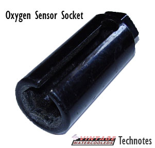
Oxygen Sensor tool - 22mm extra deep socket. It has a slot for the oxygen sensor's wire to be able to turn in.
Search Froogle for this tool
Froogle: Oxygen Sensor Socket
A universal Oxygen sensor is cheap - and easy to get. for an 8v, you can get one for between $20 and $30 from an autoparts chain. 16v cars have a heated oxygen sensor that costs more and has more wires on it. Then go get an oxygen sensor socket, usually about $10 at a parts store. It's a 22mm socket, and it's actually useful for more than just this. It works on the strut nuts on the front, and on the windshield wiper holes through the cowl. More on this with pics coming soon...
Air/Fuel Adjusting
Setting up
For the love of god - you need to make sure you have no vacuum leaks and a good clean airfilter before you do this. You need to fix all your nagging idle issues before you adjust your air/fuel ratio.
Select your car - CIS, CIS-E or Digifant II. If you do not know which injection system you have, you may not want to be messing with this just yet...
CIS
What you need
CIS cars have a frequency valve that gets turned on and off really dang fast. So, you need a dwell meter. But, I use a Craftsman Multimeter I bought at sears for $30. It can measure Duty Cycle in %. I will show how to do it with both here...
The other thing you need is a 3mm T-handle allen wrench for adjusting the mixture. it needs to have a very long shank to be able to reach all the way down there. If your car still has the aluminum plug there (rare) - you will need to drill it a bit, drill a screw in to grip the plug, and pull the whole plug/screw thing out with some pliers.
Hooking up your Meter
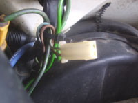
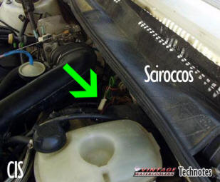
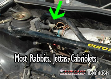
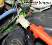
The connector you need to use is not in the same place in all cars, but you are looking for the same basic connector. It is white, with two leads in it.
This is what the plug you are looking for looks like - it has 2 small wires connected to it - one brown and one blue with a white stripe. The Dwell Meter's Green lead connects to the blue/white wire and the Dwell Meter's Black gets connected to the brown. For the Multi-meter, it's Black to brown and Red to blue/white.
 |
|
 |
 |
Start your car up, let warm up all the way. A good way to make sure it is all warmed up is to let it have run the radiator fan twice. Now turn the car off for a minute.
Dwell Meter
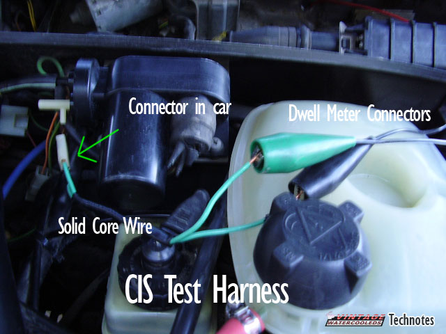
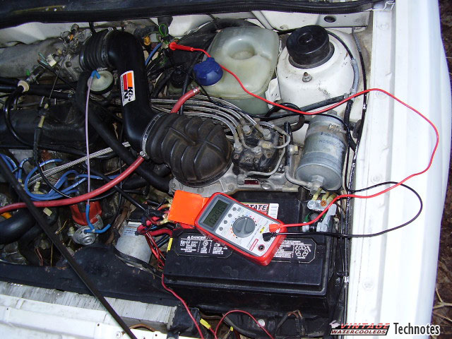
This part depends on how your meter connects. I used house wires to stuff into the connector, and then clipped the meter onto the ends. After you connect them, restart your car. Click the picture to make it bigger.
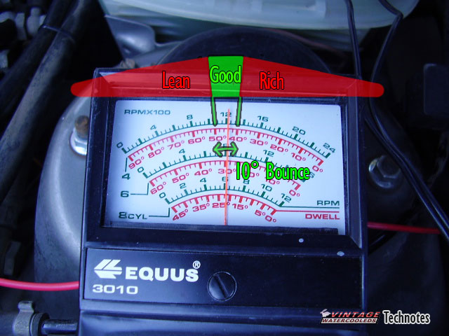
After you have your car started again, the dwell meter starts doing stuff. The needle should be sweeping about 10°. It needs to sweep in the area of 45° ± 7°. So if you are in between 38° and 52° - you are in the ideal range. If the reading is below 23° or above 59°, then you need to adjust the mixture. See the picture to the right for details... If your sweep is too wide, then you have problems like a bad oxygen sensor, bad grounds, or vacuum leaks. Fix that, then continue here.
If your needle is sweeping above 50°, then you are running too lean. If you are below 40°, then you are too rich. Running rich isn't too bad except for burning too much fuel and some black smoke under acceleration. BUT, running lean is BAD, VERY BAD!! It can fry your valves and cook your pistons, and create all kinds of problems. It can actually make your exhaust manifold and catalytic converter glow red hot! If you are out of adjustment, continue on to the adjusting part...
Digital Multimeter
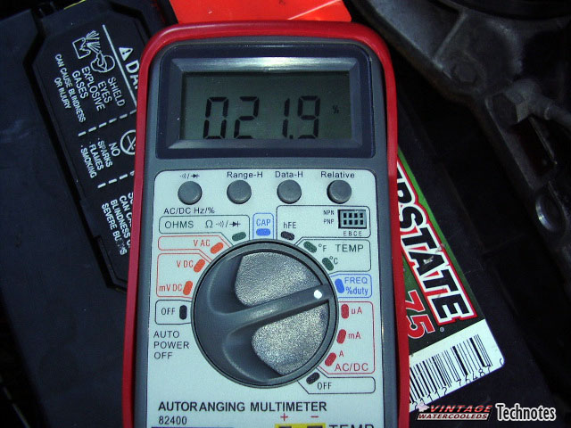
This is my new preferred method. So again, hook up the meter to the test plug and restart the car. You should see the numbers flashing in percent on your meter. Click the picture to the right to enlarge. Note how mine is way off - I have a very large exhaust leak, so I'm gonna fix that and come back and update this section later with it. The Ideal specs are to be at 50% ± 8%. So, if you are going up and down between 42% and 58% - you are good. If you read below 25% or above 65% - you will want to adjust the mixture. If you are too low, you are running rich, too high - you are running lean. Adjust accordingly...
Adjusting the mixture
To adjust the mixture, turn the Allen screw clockwise to make the mixture more rich. Turn it counterclockwise to lean it out. Your allen screw in there could be dirty and full of evil black stuff - you will just have to turn the car and dig it out so you can turn it. When you turn it, you will need to push down a bit to get the pressure necessary to turn the screw. The car will almost, or just plain die when you do this - don't worry - it's just because the air metering plate is there and you pushed it down. Make a small adjustment and restart the car and try again from there.
CIS-E
What you need
CIS-E? you have it easy. All you need is a voltmeter that can measure amps. You can go to radio shack and get one for about $20, and it will even be digital! Cool.
Your test harness is not so easy. You need to make it out of Junior power timer connectors so you can test in-line with your DPR (Differential Pressure Regulator). Mk1 Sciroccos have the male JPT connectors on their turn signals, but these are rare. Female JPT connectors are everywhere, 99% of cars made after 1990 or so have them as fuel injector connectors, They are also known as Bosch connectors. Make yourself a harness as illustrated in this picture...
Last thing you need is a 3mm T-handle Allen wrench for adjusting the mixture. it needs to have a very long shank to be able to reach all the way down there. If your car still has the aluminum plug there (rare) - you will need to drill it a bit, drill a screw in to grip the plug, and pull the whole plug/screw thing out with some pliers.
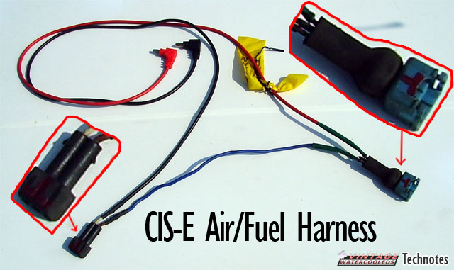
Making your test harness
This harness can be built yourself using new or junkyard parts. See the picture on the left to see what you need to make. Basically, your ammeter needs to go inline with one of the wires to the DPR. So - you need to add this chunk of harness in between the connector and the DPR itself to do that.
New Parts - I found a good site you can get these connectors on - http://www.eagleday.com/ampconnectors.html will fix you up. You need the two conductor Junior Timer AMP connectors. One male and one female. A digifant fuel rail may also have the correct Connector.
Junkyard Parts - the female connector is easy - any car with EFI will have the female plugs connected to each of it's fuel injectors. Male ones are much harder to find. You can find the male connector on the oxygen sensor wire of some cars, and also some Mk1 Sciroccos may have this connector in the front turn signal harness.
Useful VW Part Numbers
Male JPT connector is VW part number N 17 457 2Measuring the Air/Fuel Ratio
Start, and fully warm up your car. A good rule of thumb is the have the coolant fan have cycled on and off twice. Turn the car off, and connect your test harness in line with your DPR, and turn on your meter. Restart the car. The ideal value of current is 10mA ± 1mA. Adjust the air/fuel mixture if it is more than 6mA off of the spec.
(More coming soon! - I need to make a test harness and a 16v car to test!)
Adjusting the mixture
To adjust the mixture, turn the Allen screw clockwise to make the mixture more rich. Turn it counterclockwise to lean it out. Your allen screw in there could be dirty and full of evil black stuff - you will just have to turn the car and dig it out so you can turn it. When you turn it, you will need to push down a bit to get the pressure necessary to turn the screw. The car will almost, or just plain die when you do this - don't worry - it's just because the air metering plate is there and you pushed it down. Make a small adjustment and restart the car and try again from there.
Digifant II
Digifant II systems are far far more computer controlled, you should not ever have to adjust the air/fuel ratios with it. BUT - if you do - here's how! You need a very accurate CO% meter that connects to the CO tap tube on the exhaust manifold, you can't use a dwell meter or duty cycle meter for this at all. Measuring the CO tells you what the Air/Fuel ratio is.
I will post a chart/table soon with the %CO measurements.
To adjust the air/fuel ratio, there is a plug on the MAF, you need to remove this plug. Then you can get to the 5mm adjustment scew.
Fuel Enrichment for CIS-E 16v engines (BETA)
Special thanks to Rick Kellner on the Scirocco-l for this great information!!
INTRODUCTION
This is a fuel enrichment device designed to work with 16-valve
Volkswagen engines using the CIS-E (Bosch KE-Jetronic) fuel system,
for example, the Scirocco 16V. I've heard of using a similar device
on 8-valve engines which use the CIS-E system, but I don't have one
to test, so you’re on your own. This device will NOT work with
standard CIS (non -E) systems, Digifant systems, or Motronic
systems. If you don't know which system your engine uses, stop
reading now, because you probably aren't qualified to be mucking
with your engine management system.
ACKNOWLEDGEMENTS
Thanks to the following for their assistance on this project:
Chris Ng, who sent me plans for his enrichment device, which I based
mine on. Craig Castle, who also sent me plans for a similar device.
European Car, who published a good article on the Techtonics Fuel
Enrichment module in the November 1997 issue.
HOW IT WORKS
The CIS-E system monitors combustion stoichiometry, intake air rate,
engine temperature, and several other factors to determine what
fuel:air ratio to run the engine at. It controls the fuel:air ratio
with a differential pressure regulator on the fuel line. The more
current supplied to the DPR, the higher fuel pressure that is
supplied to the fuel injection system.
It has been observed that the fuel:air ratio in the 16V engine using
the CIS-E system is too lean at high RPMs. In order to correct this
situation, earlier fuel enrichment systems used a relay to add
resistance to the engine temperature sensor when the engine is
running at full throttle. This fools the CIS-E control system into
thinking the engine is in a cold operating situation, and increases
the fuel flow. The problem with this type of enrichment device is
that it increases fuel flow at all RPMs. The engine does not need
enrichment at low RPMs; in fact it makes the mixture too rich,
causing hesitation. One solution to this is to add a manual switch
to engage the system only as desired.
I decided to improve on this design by adding adjustable RPM sensing
ability. This is done by using a National Semiconductors LM2907-8
frequency to voltage converter. This is a versatile chip which is
commonly used in digital dwell meters, tachometers, capacitance
measurement devices, and ABS systems.
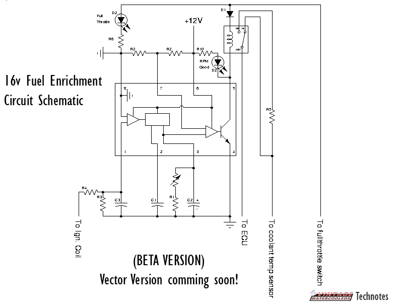
CIRCUIT DIAGRAM
Amazingly - the image compresses to 10k - so here it is...
COMPONENT LISTING
The total cost of these components was less than $20.
|
Component |
Value |
Comments |
|
Var. Resistor |
0-100 K |
adjusts RPM set point |
|
R1 |
120 K +/- 5% |
Sets max. RPM |
|
R2 |
10 K +/- 1% |
Sets reference for voltage comparator |
|
R3 |
20 K +/- 5% |
Filters input from coil |
|
R4 |
10 K +/- 5% |
Drops voltage of input from coil |
|
R5 |
1.1 K +/- 1% |
Sets enrichment value |
|
R6 |
510 +/- 5% |
Drops voltage for LED indicators |
|
C1 |
22000 pF +/- 10% |
Timing Capacitor |
|
C2 |
15 uF +/- 20% |
Controls ripple in output voltage |
|
C3 |
33000 pF +/- 10% |
Filters input from coil |
|
D1 |
1N4001 |
Prevents reverse current flow though LED indicators |
|
D2 |
5mm red LED |
Indicate status of device |
|
F-V converter |
LM2907N-8 |
RPM switch |
|
Relay |
SPDT |
Turns enrichment on |
|
Case |
1.12" x 2.5" x 3.5" |
|
|
PCB |
2.79" x 1.81" |
|
|
Cable |
7 conductors, 5 ft |
|
CONSTRUCTION NOTES
A few construction tips... Make sure your solder joints are clean
and bright. If they look "frosty", you probably moved the component
when it was still cooling, do it over.
On setting the variable resistor: The 0-100k potentiometer lets you
set the RPM switch point between 5700 RPM and 3100 RPM. You can set
it precisely by using the following formula:
R=(15/(RPM*.000000022)). R refers to the total resistance, so it
included the potentiometer value and the 120K resistor R1. Use a
digital multimeter to measure this resistance. Be sure to disconnect
the capacitor C2 first to get an accurate reading.
INSTALLATION
Mount the device somewhere convenient in the engine compartment. I
used double-sided tape to mount it under the plastic splash guard
next to the ECU.
Connect the terminal labeled "+12v" to any 12v source that is
switched with the ignition.
Connect the terminal labeled ground to any convenient ground. Note
the second ground connection in the top left corner of the circuit
diagram.
Connect the terminal labeled "To Ign. Coil" to the negative terminal
of the ignition coil.
Connect the terminal labeled "To Full throttle Switch" to the purple
wire leading from the full throttle switch on top of the throttle
body.
Locate the wires leading to the temperature sensor. It is on the
driver's side of the engine, mounted into the cylinder head behind
the cold start valve and below the thermo time switch. It is the one
on the bottom. There should be 2 wires leading from it, one brown
with a blue trace and one blue with a white trace. (Thx to
thescirocco@juno.com for this info)
Clip the blue wire with the white stripe. Splice the end that leads
to the temp sensor to the lead labeled "To Coolant Temp Sensor".
Splice the end that leads to the ECU to the lead labeled "To ECU".
You're done!
TESTING AND OPERATION
Turn the ignition switch on. Press the full throttle switch. The LED
labeled "Full Throttle" should light up. Start the engine and have a
helper slowly add throttle and monitor the tachometer. As you pass
the RPM set point, the LED labeled RPM good should light up.
Well, that's about it. Have fun.
Dan
[Back to Top] [Index] [VWC Forums] [Contact/Donate]
Remember, If you need help with any of these technotes -Contact Me!
We are not responsible for damages caused while following the directions in these pages. These pages are for informational use only.
This site is in no way affiliated with or endorsed by Volkswagen of America or VW AG. Volkswagen and the VW logo are registered trademarks of Volkswagen
AG. To visit the official Volkswagen sites go to Volkswagen Germany
or VW of America.
All original images and content Copyright © 2001-2005 Eric Soltwedel, Tim McConnell and vintagewatercooleds.com, all rights reserved.
Not all of the pages comply with the new standards yet. I have the links here for debugging purposes.
![]()
![]()
![]()
About the Standards and Scripts